I've finally wired in the Arduino Mega 2560, the Pololu servo controller, a relay board to control the track blocks and the L298 motor system to drive the trains and the tram.
It's all nicely tucked away under the layout and finally all trackwork is in place and a demo program is running which allows the train to run on every track section, exercise all the points etc.
I'll post more still shots later but for now, here's a video...
Next will have to be the 'real' software which allows for 3 engines to run on the layout at once.
Showing posts with label arduino. Show all posts
Showing posts with label arduino. Show all posts
Friday, 3 January 2014


Sunday, 29 September 2013
Using Implantable RFID Tags to identify trains
I think I'd like to be able to identify which train is which on my layout without having to type in numbers and so forth. I've decided to put a single RFID reader on the track somewhere and run all trains past it at the start of my sessions so the computers can work out what is where automagically.
I bought these nifty and tiny RFID tags from LittleBird.
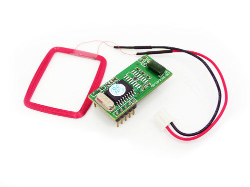
And this RFID reader with a nice TTL UART for serial transmission.

Here's the extremely simple test circuit I built using an Arduino Nano to control it all...

The antenna is the red wiring loop on the top right. The Arduino is the blue board bottom left.
Sample code is below.
//
// This code implements a state machine to read a serial stream from pin 3
// for s simple 125KHz RFID reader:
// http://www.seeedstudio.com/wiki/index.php?title=125Khz_RFID_module_-_UART
//
//
//
#include <SoftwareSerial.h>
typedef enum RFIDProtStateType { initialising,
waiting_good,
waiting_error,
started,
reading_digits,
reading_cksum,
waiting_finish,
finished };
// a global representing the current command state
RFIDProtStateType RFIDProtState;
boolean GotRFID;
char RFIDTag[10];
char Checksum[2];
int index;
#define RFIDProtRxPin 3
#define RFIDProtTxPin 2
SoftwareSerial RFIDProtSerial = SoftwareSerial(RFIDProtRxPin, RFIDProtTxPin);
void
setup()
{
Serial.begin(9600);
RFIDProtSerial.begin(9600);
index = 0;
RFIDProtState = waiting_good;
GotRFID = false;
}
//
// Convert a string containing 2 bytes representing a number in HEX into a hex byte
// ...so a string containin "A1" will be returned as 0xA1
//
byte
StringHexToByte(char *in)
{
byte result;
int j;
result = 0;
for(j = 0; j < 2 ; j ++)
{
if( in[j] >= 'A')
{
result |= (in[j] - 'A' + 10) << 4*(1-j);
}
else
{
result |= (in[j] - '0') << 4*(1-j);
}
}
return result;
}
//
//
// Handle Char will process a message coming in of the form:
//
// <0x02><10 hex digit ID tag><2 digit xor checksum><0x03>
//
// errors show up on pin 13 (with LED)
//
void
HandleCharacter(char c)
{
int i,j;
byte cksum = 0x00;
byte digit;
switch(RFIDProtState)
{
case waiting_error:
case waiting_good:
if(c == 0x02)
{
// we now have the start character
RFIDProtState = started;
index = 0;
}
else
{
RFIDProtState = waiting_error;
}
break;
case started:
case reading_digits:
if(c >= '0')
{
RFIDProtState = reading_digits;
RFIDTag[index++] = c;
if(index == 10)
{
RFIDProtState = reading_cksum;
index = 0;
}
}
else
{
RFIDProtState = waiting_error;
}
break;
case reading_cksum:
Checksum[index++] = c;
if( index == 2)
{
// we now have the 2 bytes of checksum read in
index = 0;
cksum = 0;
// calculate the checksum from the string of digits
for(i=0; i< 5;i++)
{
digit = StringHexToByte(&RFIDTag[i*2]);
cksum ^= digit;
}
if (cksum != StringHexToByte(Checksum))
RFIDProtState = waiting_error;
else
RFIDProtState = waiting_finish;
}
break;
case waiting_finish:
if(c == 0x03)
{
RFIDProtState = finished;
}
else
{
RFIDProtState = waiting_error;
index = 0;
}
//break;
// Note no break here - fall through and handle finishing
case finished:
index = 0;
GotRFID = true;
RFIDProtState = waiting_good;
break;
}
}
void
GetCommand()
{
char c;
if(RFIDProtSerial.available())
{
c = RFIDProtSerial.read();
HandleCharacter(c);
}
if (RFIDProtState == waiting_error)
digitalWrite(13, HIGH);
else
digitalWrite(13, LOW);
}
void
loop()
{
GetCommand();
if(GotRFID)
{
int i;
for(i = 0; i < 10; i++)
Serial.print(RFIDTag[i]);
Serial.println();
GotRFID = false;
}
}
I bought these nifty and tiny RFID tags from LittleBird.


And this RFID reader with a nice TTL UART for serial transmission.
Here's the extremely simple test circuit I built using an Arduino Nano to control it all...

The antenna is the red wiring loop on the top right. The Arduino is the blue board bottom left.
Sample code is below.
//
// This code implements a state machine to read a serial stream from pin 3
// for s simple 125KHz RFID reader:
// http://www.seeedstudio.com/wiki/index.php?title=125Khz_RFID_module_-_UART
//
//
//
#include <SoftwareSerial.h>
typedef enum RFIDProtStateType { initialising,
waiting_good,
waiting_error,
started,
reading_digits,
reading_cksum,
waiting_finish,
finished };
// a global representing the current command state
RFIDProtStateType RFIDProtState;
boolean GotRFID;
char RFIDTag[10];
char Checksum[2];
int index;
#define RFIDProtRxPin 3
#define RFIDProtTxPin 2
SoftwareSerial RFIDProtSerial = SoftwareSerial(RFIDProtRxPin, RFIDProtTxPin);
void
setup()
{
Serial.begin(9600);
RFIDProtSerial.begin(9600);
index = 0;
RFIDProtState = waiting_good;
GotRFID = false;
}
//
// Convert a string containing 2 bytes representing a number in HEX into a hex byte
// ...so a string containin "A1" will be returned as 0xA1
//
byte
StringHexToByte(char *in)
{
byte result;
int j;
result = 0;
for(j = 0; j < 2 ; j ++)
{
if( in[j] >= 'A')
{
result |= (in[j] - 'A' + 10) << 4*(1-j);
}
else
{
result |= (in[j] - '0') << 4*(1-j);
}
}
return result;
}
//
//
// Handle Char will process a message coming in of the form:
//
// <0x02><10 hex digit ID tag><2 digit xor checksum><0x03>
//
// errors show up on pin 13 (with LED)
//
void
HandleCharacter(char c)
{
int i,j;
byte cksum = 0x00;
byte digit;
switch(RFIDProtState)
{
case waiting_error:
case waiting_good:
if(c == 0x02)
{
// we now have the start character
RFIDProtState = started;
index = 0;
}
else
{
RFIDProtState = waiting_error;
}
break;
case started:
case reading_digits:
if(c >= '0')
{
RFIDProtState = reading_digits;
RFIDTag[index++] = c;
if(index == 10)
{
RFIDProtState = reading_cksum;
index = 0;
}
}
else
{
RFIDProtState = waiting_error;
}
break;
case reading_cksum:
Checksum[index++] = c;
if( index == 2)
{
// we now have the 2 bytes of checksum read in
index = 0;
cksum = 0;
// calculate the checksum from the string of digits
for(i=0; i< 5;i++)
{
digit = StringHexToByte(&RFIDTag[i*2]);
cksum ^= digit;
}
if (cksum != StringHexToByte(Checksum))
RFIDProtState = waiting_error;
else
RFIDProtState = waiting_finish;
}
break;
case waiting_finish:
if(c == 0x03)
{
RFIDProtState = finished;
}
else
{
RFIDProtState = waiting_error;
index = 0;
}
//break;
// Note no break here - fall through and handle finishing
case finished:
index = 0;
GotRFID = true;
RFIDProtState = waiting_good;
break;
}
}
void
GetCommand()
{
char c;
if(RFIDProtSerial.available())
{
c = RFIDProtSerial.read();
HandleCharacter(c);
}
if (RFIDProtState == waiting_error)
digitalWrite(13, HIGH);
else
digitalWrite(13, LOW);
}
void
loop()
{
GetCommand();
if(GotRFID)
{
int i;
for(i = 0; i < 10; i++)
Serial.print(RFIDTag[i]);
Serial.println();
GotRFID = false;
}
}
Sunday, 24 February 2013
All Torque No Action?
...or maybe when too little torque is, well, not enough, perhaps? No, not really.
I'm trying to control 2 points with one servo and it just proved too hard.
I did an experiment today inspired by a friend of mine - Mr Merrigan. I have a number of points for switching lines which really can only move together (unless you enjoy derailment).

Chris suggested trying to make thes emove usnig a single servo. Well, I had a red hot go at this on Saturday and a good part of Sunday morning.
The idea it to mount the motor roughly in the mid-point of the meeting switches and have a beam going out across both switches with rods hooking into the cross-bars of the switches. One motor, two moving switches in synchronicity.

 You can see the servo above and the spar above that with a nice mount point for the motor.
Just to make this a bit more obvious I have mounted the spar on top of the tracks so you can see how it would work. I've also put a videoon YouTube where I show the movement by hand.

I'm trying to control 2 points with one servo and it just proved too hard.
I did an experiment today inspired by a friend of mine - Mr Merrigan. I have a number of points for switching lines which really can only move together (unless you enjoy derailment).

Chris suggested trying to make thes emove usnig a single servo. Well, I had a red hot go at this on Saturday and a good part of Sunday morning.
The idea it to mount the motor roughly in the mid-point of the meeting switches and have a beam going out across both switches with rods hooking into the cross-bars of the switches. One motor, two moving switches in synchronicity.


Just to make this a bit more obvious I have mounted the spar on top of the tracks so you can see how it would work. I've also put a videoon YouTube where I show the movement by hand.

Now this looks like a great idea but in fact it does not work well for a lot of reasons:
- You need very careful alignment to make this work and that is not insurmountable but is hard.
- The motion of the corss bar is straight across but this is radial and so puts more strain on the motor at the extremes of the switch positions. That's not a problem - just use a big motor. But that means a $20 motor instead of 2 x $4 = $8 :-(
- The long central spar (15cm) means that even a small turn of the motor (1 deg) results in a big movement, so your points no longer switch nice and smoothly.
I tried and tried but no luck. When I thought through the logic I realise it was a dead loss really.
For all of these reasons, I'm moving back to one cheap servo per point. Sorry Chirs, nice idea though.
I've got my servo mounting system down to about 10 minutes per point.
Of course, there are other ways to do the mechanism so 1 servo will drive 2 points but it then takes more than 10 minutes per point to mount!
Sunday, 6 May 2012
Arduino and Shift Registers - How Fast Is It?
I'm currently driving my test layout using an old Arduino Diecimila and a L298 dual motor controller shield from DFRobot.
This simply won't cut it in the long run. I will need to run more motor controllers and I want some flexibility around how to mount the motors - not as a shield. I found some very nice cheap controllers on DealExtreme for the outrageous price of $6.70 each. For this you get a full dual motor driver which can also be used for steppers. Only problem is it takes 6 lines to drive (3 per motor) instead of the 4 of the Shield. I need to drive the PWM direct from the Arduino. However, the direction logic now uses 2 lines per motor, not just 1, so I will need to use more shift registers to handle this to keep as many other I/O pins as possible free on the Arduino.
I now have a total of 48 bits of output from shift registers driven by 2 3 pin interfaces. Thats for bits of output for only 6 pins.
The real issue for me is how fast I can hammer the pins on a shift register from an Arduino. It turns out, pretty fast. Fast enough to do basic PWM with an LED.
You can see that the LED on the top left is pulsing in brightness. The LED on the right is simply flashing on and off as a heart-beat.
This is a nice little 24-bit setup. Looks like I can run 2 lots of 24-bits very effectively.
Next time I will test 48 bits from 3 pins on the Arduino.
This is a nice little 24-bit setup. Looks like I can run 2 lots of 24-bits very effectively.
Next time I will test 48 bits from 3 pins on the Arduino.
How about 8 points per Arduino?
So I have constructed my nice point motor controller using servo motors and an Arduino - very nice, thank you.
However, now I have a layout that needs to control 8 points, not 4. I also have limited I/O lines on the main controller so dedicating 8 to driving the point controller is just too much.
I decided to control all 8 points from a single Arduino and use the serial port to control the position and calibration of the points. I still use a pot to control the calibration process because it's just so intuitive.
This posed quite a few challenges. Firstly, don't try doing this with an Arduino Diecimila - you need a newer system than that - I used a Freetronics TwentyTen (discontinued) but the Eleven will be fine as well.
The other consideration is POWER. Yes, sorry but it's not going to work from USB and it's not even going to work well from a PC power supply without a little help. Yes, I'm talking about large capacitors and even a diode for return current.
Have a look at the photos below...


Friday, 6 April 2012
Some video of the new layout.
I've been running my engines using a very poor old wower unit. I got really tired of it today and did a quick hack job on an Arduino system to run 2 trains using 2 pots to control spped and direction. Nice and easy - took me 20 minutes total.
Anyway, here's some nice videos of it all running...
Subscribe to:
Posts (Atom)